
Trimming in Alias
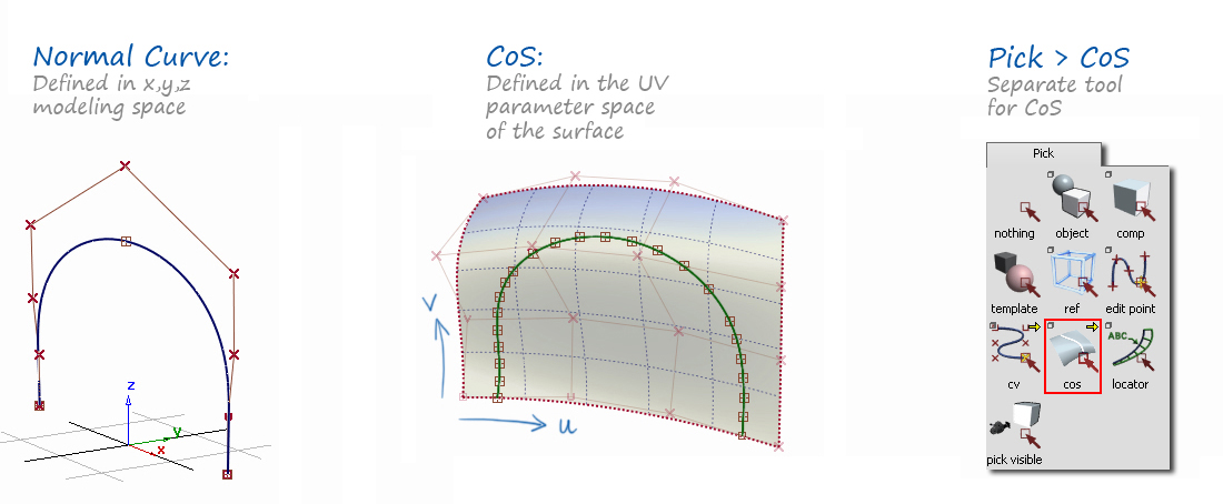
Many CAD systems modify a surface directly using a normal curve:

In Alias there is an intermediate step required for trimming, the creation of a Curve-on-Surface:

Curves-on-Surface
A Curve-on-Surface is often referred to in the Alias interface as a 'CoS'. It works differently to a normal NURBS or Bezier curve defined in the x, y, z modelling space in the following ways:
- A CoS is defined in the UV parameter space of the surface it lies on and cannot move away from that surface.
- It's modifiable by hand using Pick → Edit Point only, and has no CVs.
- It's created by Alias as a Degree 3 curve (typically multi-span) - the user has no control over this parameterisation.
- It's selected using a separate tool on the Pick Palette: Pick → COS.
Tools for Creating Curves-on-Surface
On the Surface Edit Palette, there are three tools for creating CoS, of which the first two are the most commonly used:
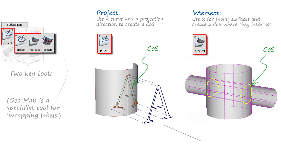
Note: There is also a freehand drawing tool on the Curve Palette. This requires you to position the Edit Points of the CoS directly onto the UV parameters of the surface, a method which is unpredictable. So for most situations, the projection method (above) is preferred as this allows you to control the shape more easily by CV manipulation.

Tools for Using Curves-on-Surface
- The primary use of the Curve on Surface is to trim the surface using Surface Edit → Trim.

- Curve Edit → Create → Duplicate will make a copy of the CoS as a normal curve.
- Curve Edit → Fit Curve can also be used to create a normal curve from the CoS, but with more control over the parameterisation and fit.
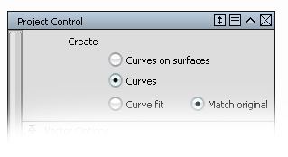
- Set the Surface Edit → Project tool to create Curves instead of CoS.
- Surface Edit → Trim Convert. If a trimmed surface results in a four-sided boundary, then Trim convert can create a natural edged 4-sided surface from it.
Accuracy of Curves-on-Surface and Trimming
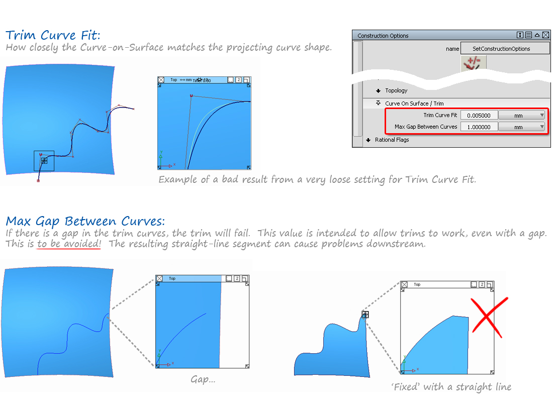
There is a specific section in the Preferences → Construction Options called Curve on Surface / Trim where tolerances are set for trimming:
- Trim Curve Fit. Determines how accurately the CoS matches the curve that is being projected. This is typically set to the same or smaller than the Max Gap Distance and Curve Fit Distance, for example 0.001mm.
- Max Gap Between Curves. Some of the default settings are as large as 1mm. This should be set to a much tighter value, for example 0.001mm, for accurate modelling.
Understanding Natural and Trimmed Edges
A surface can be cut by Detaching or Trimming, and it's important to understand the difference:
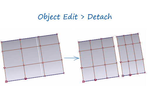 | | 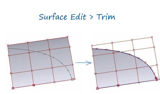 |
| Can only happen in the direction of the isoparms | --- | Can have any shape - created by curves-on-surface |
| Will always result in a four-sided boundary | --- | Can create any number of boundaries |
| Edges will be Natural surface edges | --- | The Trimmed edges will have more complex parameterisation |
| The cut cannot be restored using Object Edit → Attach | --- | The cut can be restored using Surface Edit → Un-Trim |
| ICEMsurf equivalent tool: Trim to Iso-Curves | --- | ICEMsurf equivalent tool: Face |
