Construction Tolerances
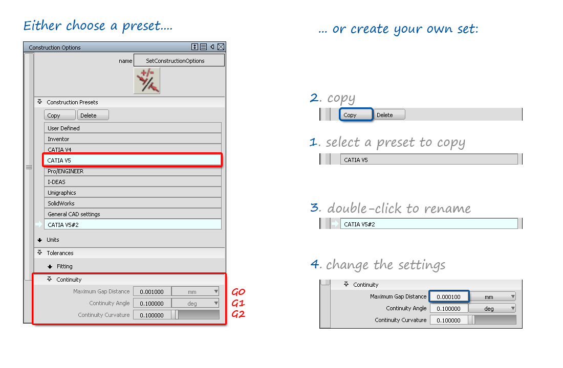
Tolerances are chosen using Preferences → Construction Options. They specify the numerical thresholds that geometry calculations are made to, and are mostly used to create 'watertight' models that will successfully export into Engineering CAD or Manufacturing systems.
Most users settle into using one set of tolerances, either one of the presets (i.e. Catia V5) or a customised set created by them or used as a company standard.
The key values are the Continuity settings that relate to G0, G1 and G2.
Failing to Achieve Tolerances
The practical reality of modelling means that a surface will often fail to achieve a particular tolerance exactly. This is normal, and experienced modellers learn to judge when a surface has to be rebuilt to satisfy the tolerance requirement, and when the result is good enough for the task in hand.
G0, G1, G2 Measurements
The G0, G1 and G2 measurements are made where two surface patches meet:

These measurements are important for different things:
G0 Position - Important for Data Transfer
This tolerance is important for creating a 'closed' model, either for prototype or manufacture into a real, physical object, or for transfer into a solid-modelling CAD system for engineering detailing.
You may need to experiment with some test transfers to find the correct tolerances for your workflow. Construction pre-sets are available for common downstream CAD systems.
G1 Tangent - Important for Physical Smoothness
A tangent break of less than 0.1 degrees will normally not be visible on most products, and so working within these limits will make sure there are no unwanted 'sharp' edges between surface patches that should represent a smooth shape.
G2 Curvature - Important for Visual Smoothness
The value for Curvature Deviation is calculated as (Radius1 - Radius2) / (Radius1 + Radius2). This is used by Alias for internal calculations, but isn't really useful to a designer.
In practice, a numerical 'fail' is useful to alert your attention to a possible problem, but design decisions are made on the result of the visual analyses. (See the two Evaluation Theory Builders for more details).
Recommended Construction Tolerances
Each company will typically develop their own recommended tolerances that work for their data pipeline.
If you are working independently, or want a recommendation, then use the General CAD settings.
Many users have different sets of tolerances they use at different stages of the design process:
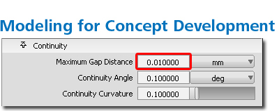 | If you are creating a concept model that won't be used for production, then it is acceptable to use looser tolerances, to speed up calculation time and keep surfaces light. Examples would be models for rendering or animation, or early iterations and exploratory models. |
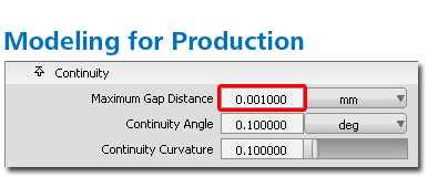 | If your model will be used for prototyping or production, it is essential that you select a tight set of tolerances before you start to create surfaces. The precise choice will depend on the product, the materials and the production process used, but a typical Maximum Gap Distance would be between 0.01mm and 0.001mm |
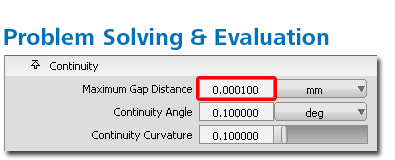 | Very tight tolerances are usually only set temporarily for problem solving (building surfaces at a tighter tolerance can solve some stitching problems). They can also be used to get more detailed feedback from the Continuity Check tool when building to Class A standards. |
Checking Construction Tolerances
Alias uses a boundary locator to evaluate the numerical continuity between two surface patches.
It displays as a green when a boundary is within tolerance, and yellow/red when it fails.
The letters P, T, C - Position (G0), Tangent (G1,) Curvature (G2) - are displayed to show which level of continuity has passed or failed.
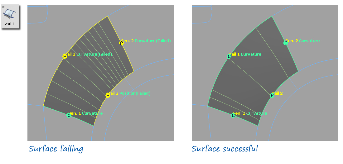
There are two ways to apply this locator:
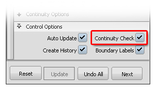
In most surface tool control windows, there is a Continuity Check option which automatically displays the continuity achieved.
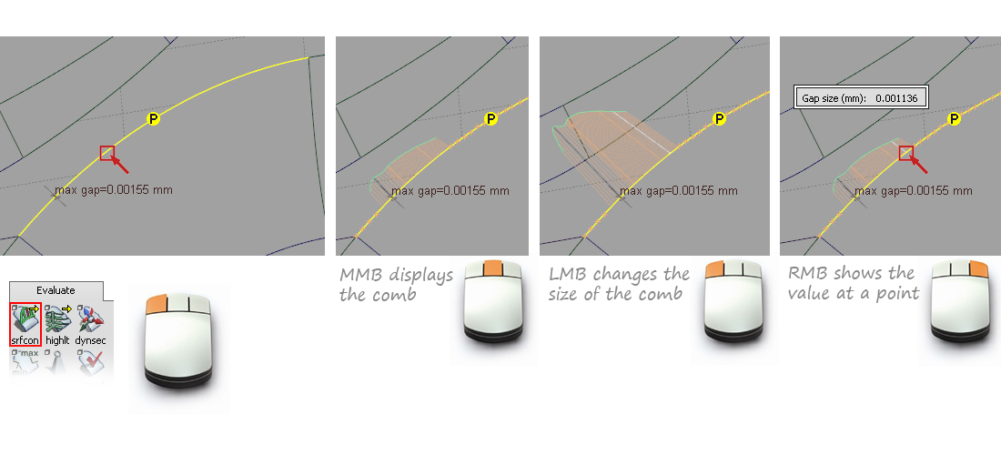
Alternatively, Evaluate → Continuity → Surface Continuity can be used to check a specific boundary. This tool has more options for displaying detailed information:
To check the whole model for G0, G1 and G2, use Evaluate → Model Check.
Stitching a Model
The Surface Edit → Stitch tool is used to create 'solid' models, typically for export. The stitch tool checks for Position Continuity (G0) only, but is a useful, quick way to check for gaps.
It is less accurate than the Evaluate → Continuity → Surface Continuity tool, so any gaps highlighted by stitching should be 'double-checked' using the Continuity Check tool.
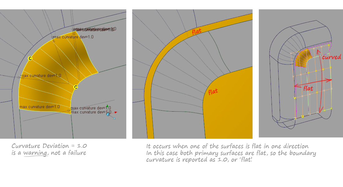
Note: 'Flat' Curvature
A 'flat' curvature is shown as a 'fail', but is usually not a problem and can be ignored.
