
Introduction
As you use the tools in Alias to create your designs, you will need to use the NURBS terminology to specify what you want. We, as human designers, can imagine or sketch shapes with a pencil or even by waving our arms around in the air, but the software needs more explicit, compact instructions.
This theory-builder shows you how the mathematical terminology relates to the shapes you want to create.
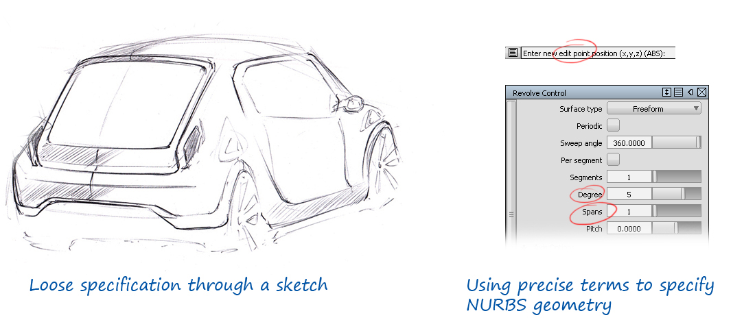
NURBS Terminology
All the terminology you need to use for creating curves and surfaces is shown in the Display section of the Control Panel. To keep things simple, the first sections consider curves only, though all the concepts apply equally to surfaces.

Control Vertices (CVs)
Control Vertices (CVs) are the main way in which we control the shape of both curves and surfaces. As designers, we want to be able to push and pull CVs to achieve the shape we want.
This can be done simply by using Pick → CV and Transform → Move to change the positions.

But it is also important to be able to choose the number of CVs, and to do this we need to understand Spans and Degree.
Spans
A span is like a single strip of a material such as wood or metal, a flexible, but quite stiff material that can be bent into a smooth shape.

A curve can be thought of as a strip (or span) of NURBS 'material'.
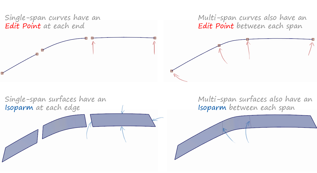
It has CVs (as shown in the previous section), but it also has Edit Points that define the start and end of a span. Here are some examples of single-span curves which have an Edit Point at each end:

To get a longer, more complex shape, there are two approaches:
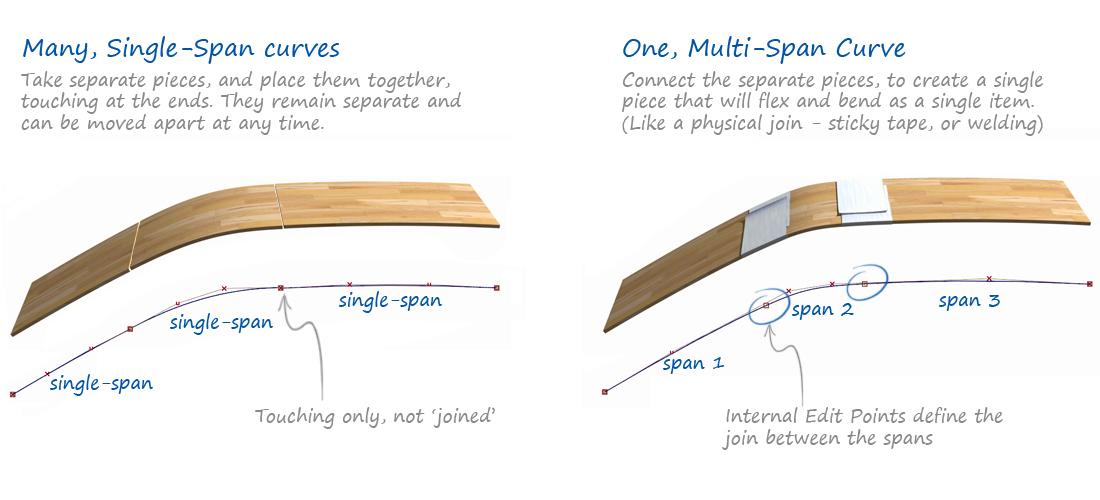
Understanding the benefits and disadvantages of these two different approaches is at the heart of good modelling practice with NURBS geometry, and is covered in detail in the third Golden Rule.
For now, it is enough to understand that increasing the number of spans will increase the number of CVs in the curve.
There is however another factor that also affects the number of CVs - the Degree.
Degree
Mathematically, degree is the related to the highest power (or exponent, or index) in the equation used for the curve or surface. The more 'math' in an equation, the more CVs there are in the curve, and so the more flexible the curve can be.
Here is a very simplified example of an equation to illustrate the degree:
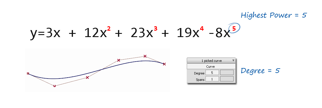
As designers, we aren't interested in the math. All we need to know is that increasing the degree will increase the number of CVs in the curve.
Number of CVs
So, both the Degree and the number of Spans affect the number of CVs in a curve, and they are linked via this formula:

The easiest way to apply this is simply to add up the two numbers shown in the Control Panel for the Degree and Spans of the chosen object.

So there are two ways to achieve a particular number of CVs in a curve: increase the Degree, and/or increase the number of Spans.

Throughout this course you will be shown examples where you decide which method to use. Mostly we choose to use single-span and use the Degree to modify the number of CVs. See the Bezier section below for more details.
Other Terminology
Bezier
Bezier mathematics is a subset of the NURBS mathematics used in Alias.
A NURBS curve or surface which is single-span is exactly equivalent to a Bezier curve or surface. Because Alias works with both single and multi-span NURBS, it doesn't use the term 'Bezier' often, but whenever the spans are shown as '1', then the mathematics being used is Bezier math.
Working with Bezier math is simply a choice the user makes to limit themselves to using only Single-Span curves and surfaces. The benefit is that each curve or surface is inherently smooth. See the third Golden Rule for more details.
Edit Points and Isoparms
CVs exist on curves and surfaces, and work in the same way on both.
Edit Points however only exist on curves. The equivalent on a surface is called an Isoparm line. They both have the same function, which is to show the span structure - either single-span or multi-span.
U & V Parameters
CVs and Hulls can be used in exactly the same way on surfaces as on curves - they are selected and moved to control the shape.
The only difference is that a curve has one direction (U) and a surface has two (U and V). The first and second CVs are always displayed differently to show the U and V directions.
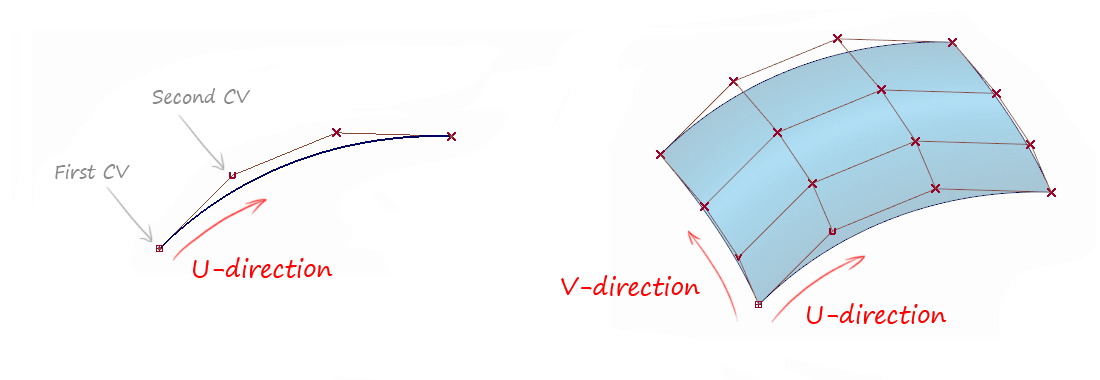
The U and V represent the 'parameter' value from one end of a curve or surface to the other. This is used in the math to generate the curve or surface, but we use it simply to identify the directions on a curve or surface.
Most of the time, the direction isn't relevant to the shapes we create and we can ignore it. There are a few situations where direction is important, such as a twisted surface, and there are tools to reverse the direction when needed.
Curve & Surface 'Normals'
The 'Normal' direction is at 90 degrees the curve or surface direction, and it is always linked to the U and V parameter directions:

Hulls
In the illustration above, the CVs are displayed with thin red lines connecting them. These are called hulls and they serve two purposes:
- To allow selection of a complete row of CVs on a surface (using Pick → Hull).
- To give a visual indication of the flow of the CVs across a curve or surface.
Although Hulls are the last topic in this Theory Builder, they are really important for visualising the flow of CVs across a surface, which in turn is what creates surfaces with good tension and highlights.
Picking and moving Hulls is also an important way of modifying surfaces while maintaining some discipline across the flow of CVs.
